Simtec USB technical
The Simtec USB stack may be found in the Simtec USB podule, the Stuart Tyrrell Developments UNIPod and the A9Home computer from Advantage6. As standard it provides USB keyboard and mouse drivers and a Mass Storage driver for USB flash and hard drives.
Note: the information on this page has mostly been established through unofficial channels and experimentation, and has a high chance of being wrong. It is not supported by Simtec or STD and may be subject to change in future versions of the USB firmware.
USB stack
The Simtec USB stack and HID drivers are poorly documented.
USB stack introduction riscos-usb.org site: low-level API description
HID drivers
The mouse drivers don't use the RISC OS 3.5+ mouse driver interface. This means they work in parallel with the configured mouse: a USB mouse and a quadrature mouse can work at the same time. It is suspected it inserts mouse events into PointerV instead. The scrollwheel is supported on RISC OS Adjust, using the WindowScroll module to move windows; on Adjust OS_Pointer provides an interface to read scrollwheel events (see Adjust documentation or StrongHelp OS manual).
MassFS 1.00
This information relates to MassFS 1.00 as supplied with Simtec USB cards and Unipods.
MassFS supports only USB Mass Storage devices with class:subclass:protocol of 08:06:50, that is, "Mass Storage:SCSI transparent command set:Bulk-only transport". This group includes most pen drives. It doesn't support devices that use the ATAPI subclass.
Plug in a USB drive and it appears with its name on the iconbar, eg USB_DISK, with hard spaces (Alt-160) replacing spaces in the DOS disc name. Drives available may be enumerated:
SWI MassFS_GetDriveCount (&56700)
- On exit:
- r0 = number of drives managed by MassFS
SWI MassFS_GetDriveInfo (&56701)
- On entry:
- r0 = drive number (from zero to number of drives managed by MassFS minus one)
- On exit:
- r0 = ?
- r1 -> drive name
- r1+20 -> connection?:drive_name:vendor_id:product_id (separated by colons, &3A)
- r2 = size in sectors (512 bytes each)
- r3 = flags?
Apart from GetDriveCount, some other MassFS_ SWIs use the drive name as parameter in r0.
MassFS presents the drive as a single file of filetype DOSDisc. This is then openable using DOSFS. This means native (FileCore) formatted flash drives aren't supported, though it might be possible using a FileCore image filing system such as FCFS. It doesn't support devices over 2GB (due to the limitations of the RISC OS image filing systems) and doesn't provide any means to access the raw sector data of such devices. It appears devices larger than 2GB aren't recognised even if they have a partition smaller than 2GB. It doesn't support DOS-style physical/logical partitioning of drives (not to be confused with DOS formatting which it does support)
To save off a DOSDisc image of the disc, do
*Copy MassFS::USB_DISK.$ ADFS::HardDisc.$.usbimage
To format the disc as FAT16 (DOS) format, use MkDOSDisc from the PC card sources (download the 3.06 source and extract MkDOSDisc from inside PCConfig/MKDOSdisc/ ). To format as 32MByte, do
*MkDOSDisc MassFS::USB_DISK.$ 32 -initdos
Don't try to format the disc larger than the size it actually is: it might be worth stepping down a megabyte or two from the published size, and beware that some devices are measured in sizes of million bytes (i.e. 32MB is 32,000,000 bytes rather than 32*1024*1024 bytes). This may need a slightly tweaked formatter to work on RISC OS 4.0 rather than 4.3x.
To read the raw blocks of a disc, open as a file then use OS_GBPB 3/4:
DIM block% 512
handle%=OPENIN("MassFS::USB_DISK.$")
address%=&4000
SYS "OS_GBPB",3,handle%,block%,512,address% TO ,,,not_read%
CLOSE#handle%
Reads 512 bytes from the disc starting at offset &4000. Writing is believed to work in the same way.
To eject a USB Zip disc:
drive$="USB_DISK"
DIM block% 12
block%!0=&1B
block%!4=2
block%!8=0
SYS "MassFS_DriveOp",drive$,0,block%,12,0,0 TO err%:REM SWI &56706
IF err%>0 SYS "MassFS_CodeToError",err% TO err%:REM SWI &56707
This looks like a SCSI START/STOP UNIT command. It might be possible to send other SCSI commands to MassFS devices in a similar way.
MassFS_DriveOp (&56706)
- On entry
- R0 -> Pointer to device name
- R1 -> Direction (0 = data out, 1 = data in)
- R2 -> Pointer to command block (SCSI)
- R3 -> Length of command block
- R4 -> Pointer to data block
- R5 -> Length of data block
- On exit:
- R0 = 0 if successful
- = Otherwise, bitfield containing SCSI error sense code
- = 0..7 = Sense key
- = 8..15 = Sense code
- = 16..23 = Sense qualifier
- = 24..31 = Sense valid
- R1 = Number of bytes transferred
MassFS 2
MassFS versions near 2 (such as 1.98) are supplied with the A9home. It is extended with a FileCore interface which enables it to support FileCore formatted discs (ie E or E+ format). This also allows it to support drives over 2GB in FileCore format only.
FileCore support is implemented with a second filing system, MassFC, which supports two FileCore formatted discs at any one time. If a device is flagged as being FileCore formatted, MassFSFiler will check if it is and if so open MassFC::<name>.$ and if not open it as FAT16 format with MassFS::<name>.$ There remains one module MassFS that calls OS_FSControl to create the MassFS filing system and FileCore_Create to create the MassFC filing system.
MassFS 2 provides the MassFS_SectorOp command for raw access to a disc, but only after it's been detected as FileCore format. Other Filecore-based SWIs (DescribeDisc, Drives etc) aren't provided (if you want this information you'll have to use MassFS' other SWIs).
MassFS SWIs
MassFS_GetDriveCount (&56700)
MassFS_GetDriveInfo (&56701)
MassFS_SetDriveInfo (&56702)
MassFS_GetStatusCount (&56703)
MassFS_FreeHandler (&56704)
MassFS_GetLastMessage (&56705)
MassFS_DriveOp (&56706)
MassFS_CodeToError (&56707)
MassFS_TestUnitReady (&56708)
MassFS_GetExtraInfo (&56709)
MassFS_IdentifyFormat (&5670A) (v2 only)
MassFS_SetModified (&5670B) (v2 only)
MassFS_SectorOp (&5670C) (v2 only)
OtherDevs file
The !MassFS.OtherDevs file is a way of tweaking various options to persuade MassFS to work with a USB Mass Storage device. It won't help if the device is not supported by the underlying USB stack, if it is not detected by *USBDevices, or hangs *USBDevices. It consists of a list of entries VVVV:PPPP=FFFFF where
- VVVV: 4 digit hex vendor ID
- PPPP: 4 digit hex product ID
- FFFFF: alphanumeric codes describing flag settings for this device.
The codes mean as follows:
- U: do not attempt to support this device (in case it's accidentally inserted)
- w: disable writing (make read-only)
- R: is a card reader
- r: might be a card reader, so check
- L: correctly supports "get maximum LUNs" command
- 2: has 2 LUNs
- 3: has 3 LUNs
- and so on until
- 8: has 8 LUNs
- Q: doesn't support Request Sense
- q: supports Request Sense if an error occurs
- _: supports reset recovery (experimental)
- T: requires test before Read Size
- t: doesn't support START up command
- C: supports READ CAPACITY (if not, READ FORMAT CAPACITIES will be used instead)
- F: FileCore formatted disc (MassFS 2)
For example:
# Device: TwinMOS 256MB Pen Drive
# Submitted by CJE
126f:2035=LR_T
The default is:
- supported
- may be written to
- not a card reader
- maximum LUNs may be read correctly
- if we can't read the number of LUNs, it has 1 LUN
- supports Request Sense all the time
- doesn't support reset recovery
- doesn't require test before Read Size
- supports START up
- supports READ FORMAT CAPACITIES
Hardware
Both Simtec USB podule and Unipod use a NXP/Philips ISP1161 controller.
The ISP1161 has four 16-bit registers, two for the host controller interface and two for the device controller interface. Both work on a command basis - a 16-bit command is written to the command register, then one or more 16 bit words are read from or written to the data register. The top bit of the command byte indicates whether it is a read or write operation.
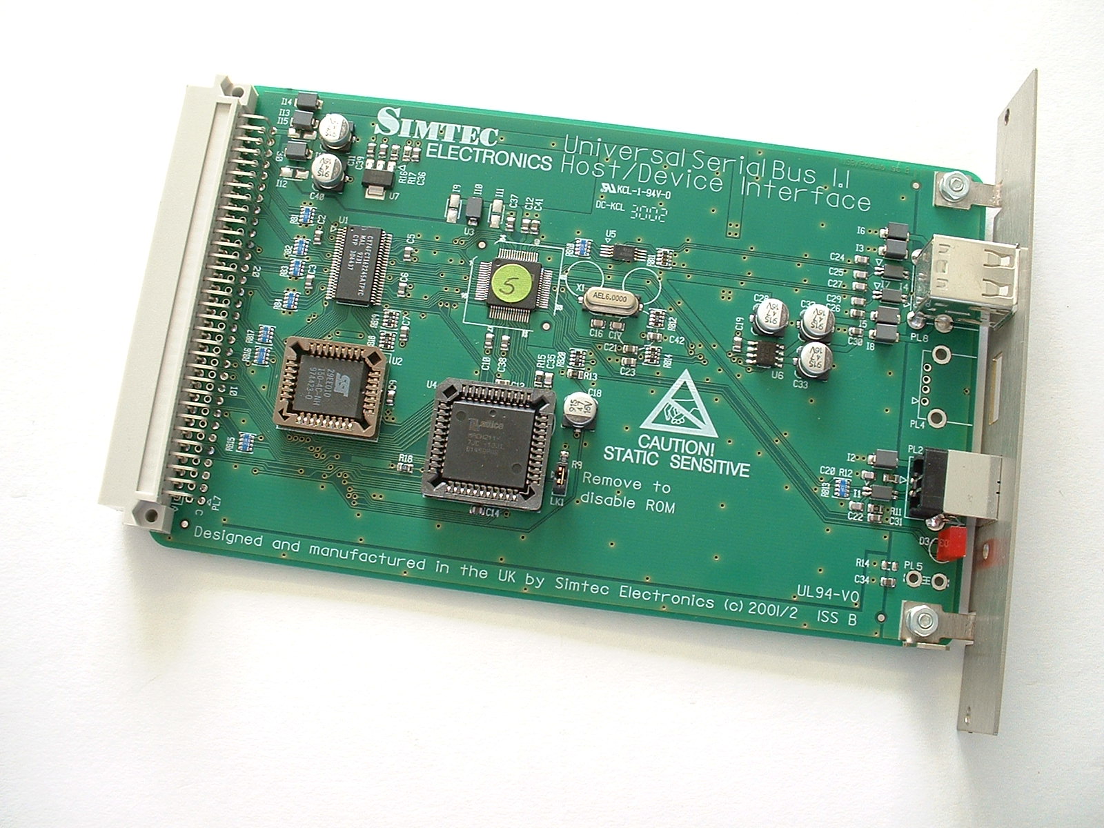
On the USB podule there's also a 29EE010 128Kx8 bit flash EEPROM, a Lattice MACH211-7JC CPLD and a 5V-3.3V level shifter (various manufacturers, eg 74FCT16245). The memory map of IOC and EASI space on the podule goes as follows:
| Register | Offset |
|---|---|
| Podule ROM | &0-&1FFC |
| Host controller data port | &2000 |
| Host controller command port | &2080 |
| Device controller data port | &2100 |
| Device controller command port | &2180 |
| Interrupt status register (read only) | &2200 |
| Interrupt mask register | &2280 |
| ROM paging register (write only?) | &2300 |
| Information register (read only) | &2380 |
Lower address bits are not decoded. That means to read 16 bytes from the host data port you can just do:
LDR r8,PoduleBaseAddress
ADD r8,r8,#&2000
LDMIA r8,{r0-r7}
(and then cut out the bottom 16 bits of each word), which on some hardware is quicker than doing lots of LDRs.
So, to read the HcChipId register (&27) use the following algorithm:
easi%=&88000000:REM EASI address of podule 0 - find this from Podule_ReadInfo
host_data_port%=&2000
host_cmd_port%=&2080
easi%!host_cmd_port%=&27:REM write command HcChipId
chipid%=(easi%!host_data_port%) AND &FFFF:REM read 16 bit result
PRINT ~chipid%
This is just an example - the accesses need to be in supervisor mode so you can't make them from BASIC. Don't forget, if you are writing to the IOC space addresses, the 16 bits of data need to be in bits 16-31 of the 32 bit word you write. The same works on the device controller, only the command DcChipId is &B5.
The ISP1161 provides two interrupt lines - INT1 for the host controller and INT2 for the device controller. The podule bus has one shared line, so it is most likely the CPLD provides two or three bits of interrupt status and control. There are two pairs of DMA pins, one pair for each of host/device. These are wired to the CPLD and the CPLD drives the DMA pins on the podule bus (it's not clear whether Simtec's driver actually uses these). So there may also be another two or three bits of DMA control.
From experimentation, these appear to be the layout of the registers:
Information register:
| Bit | Function |
|---|---|
| 0 | Global interrupt status |
| 1-4 | Board revision: 0000 for 'A' to 1111 for 'P' |
| 5 | Host controller interrupt status (unmasked) |
| 6 | Device controller interrupt status (unmasked) |
| 7 | ? |
Interrupt status/mask registers:
| Bit | Function |
|---|---|
| 0 | Global interrupt |
| 5 | Host controller interrupt |
| 6 | Device controller interrupt |
The interrupt status register is the bitwise AND of the mask register and the interrupt bits in the information register (which come directly from the USB controller). If bit 0 of the status register is 1, the device is currently asserting the podule interrupt line. The interrupt service routine can use bits 5 and 6 to work out which device is causing the interrupt.
How the interrupt arrangement was worked out
The bit layout in the interrupt control registers is a bit tricky to determine. The ISP1161 allows both polarities of interrupts, level and edge triggered. So here's what I did:
- Kill any USB software
- Turn off podule interrupts in the IOMD (otherwise we'll crash - but stops any other podules working).
- Read IOMD's podule interrupt status bit to check there are no pending interrupts from elsewhere (removing other podules is a good idea, or else pull out network cables).
- Read the state of the podule CPLD's supposed interrupt control and status registers
- Issue a read of HcHardwareConfiguration on the USB host controller
- That'll tell us what state the interrupts should be in
- Flip the InterruptOutputPolarity bit in the HcHardwareConfiguration register and write back to the host controller. Lo and behold, we're causing an interrupt!
- Check we are really causing an interrupt, by looking at the podule interrupt status bit in IOMD.
- Now look at the CPLD's interrupt status register to check it's changed
- Poke around the CPLD's interrupt control register until we can see it clear the interrupt status bit in IOMD
- Put the InterruptOutputPolarity bit back to normal.
- Do the same to the INTPOL bit of the DcHardwareConfiguration to work out the arrangement for the device controller
References
Postings by Jason Tribbeck:
- MassFS eject
- MassFS formatting
- FileCore support
- Mass storage classes
- USB Mass Storage specification: SCSI commands
Other sites: